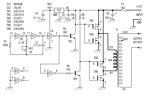
On this page, I will explain DC/AC invertor with center-tapless transformer.As for the DC/AC invertor with center-tap transformer, refer to "DC/AC invertor (1)".The invertor that I made this time uses power MOS FET as swtching device. I assum that this unit is used with the battery of car. So, the input voltage is +12V DC. The output voltage is AC 100V. However, input and output voltages aren't limited to this. You can use any voltage. They depend on the transformer to use. The wave form of the output is square wave. In my experience, it is usable with a lot of home electronics equipment. The electric power which is possible to handle is decided by the transformer to use. This time, I am using the transformer with 12V-10A(secondary side). So, it is possible to handle 120VA(about 100W).I was asked about 220V output from some readers. The output voltage of the inverter is decided only in the transformer. You can use the transformer with 220V as for primary(input) and 12V as for secondary(output). At my circuit, primary and secondary should be used oppositely. Then, you will be able to get AC220V from DC12V.
FUSE must be put, because the excessive input current flows when the oscillator stops.
Circuit drawingof DC/AC inverter (2)

Circuit explanation of DC/AC inverter (2)
The square wave oscillatorThis is the square wave oscillator which used a CMOS-type logic inverters. I use the word "logic inverter" to avoid confusion with the DC/AC inverter. The output of the oscillator is connected with the drive circuit through the logic inverters. The antiphase signal of the alternating current is created using the logic inverter, too. Connect the input of the logic inverters not to be using with the grounding to avoid bad influence.As for the operation of the oscillator which used logic inverters, refer to "Square wave oscillator (2)".I chose resistance and capacitor for the oscillator in the following value. I calculated that it was possible to set to 50 Hz or 60 Hz with the variable resistor. Because there is an error of the part in the actual circuit, it is a reference value.
Minimum frequency
F= 1/( 2.2 x C x R )
= 1/( 2.2 x 2.2 x 10-6 x 4.2 x 103 )
= 1/( 20.328 x 10⁻³ )
= 49.2 Hz
Maximum frequency
F= 1/( 2.2 x C x R )
= 1/( 2.2 x 2.2 x 10-6 x 2.2 x 103 )
= 1/( 10.648 x 10⁻³ )
= 93.9 Hz
In the measurement result in the actual circuit,the minimum frequency was 43.6 Hz and the maximum frequency was to 76.6 Hz be.
The FET drive circuitBecause the output of the oscillator is the TTL of 0V to 5V, it is converted into the amplitude of vibration of 0V to 12V to drive an FET with this circuit. It is not a special circuit.
The power MOS FET switching circuitThis is the switching circuit which is the main circuit of the DC/AC inverter this time. I used C-MOS FET circuit by power MOS FET. Two sets of C-MOS FET circuits are used and are controlled by the antiphase.
In case of the input of TR3 and TR4 are L level and the input of TR5 and TR6 are H level, TR3 and TR6 become ON condition and TR4 and TR5 become OFF condition. Therefore, the electric current flows through the direction of A to B to the secondary coil(12V side) of the transformer.When the input level is opposite, TR3 and TR6 become OFF condition and TR4 and TR5 become ON condition. Therefore, the electric current which flows through the transformer becomes contrary to the case of the above.Either above-mentioned condition is continued when the oscillator stops. Therefore, the big electric current flows on the secondary side of the transformer. The fuse must be put to protect.Refer to "The operation principle of C-MOS FET" about MOS FET and the C-MOS circuit.
The +5V power circuitThis is the circuit which is used 3 terminal regulator for +5V. It is OK with the 100mA type because it is only to drive IC1.

4 comments:
hello...i want to know if i can replace the MOSFET with another type of MOSFET...i try with IRF530 MOSFET but it explode and some of the wire burn out...if i want to replace the MOSFET, how about the connection between MOSFET?is it the same as in your circuit diagram with source connect to +12V and drain connect with another MOSFET drain?i want to replace all the MOSFET with IRFZ44N which is N-channel MOSFET..can u help me..thankz a lot..
hello...i want to know if i can replace the MOSFET with another type of MOSFET...i try with IRF530 MOSFET but it explode and some of the wire burn out...if i want to replace the MOSFET, how about the connection between MOSFET?is it the same as in your circuit diagram with source connect to +12V and drain connect with another MOSFET drain?i want to replace all the MOSFET with IRFZ44N which is N-channel MOSFET..can u help me..thankz a lot..
Tel me the advantage of this type inverter transformers over the traditional 3 pin(12-0-12) transformers.
Post a Comment